Rocket Nozzle FEA
1. Engineering Data
Materials: The main part of the nozzle uses 300 series stainless steel, and the bolt and nut holding the mid and lower nozzle together use A-286 steel.
2. Geometry
In order to analyze the rocket nozzle more easily, only one slice of the whole nozzle was taken. Also, in order to simplify hand calculations to verify the ANSYS solver’s solution, the shape was simplified into a slice of a cone, rather than a converging-diverging nozzle. The reason that this simplifies the geometry because it allows for the hoop stress formula (σ = Pr/t) to be used. Though this does greatly simplify the calculations, there is little difference in the answers of the cone and the nozzle.
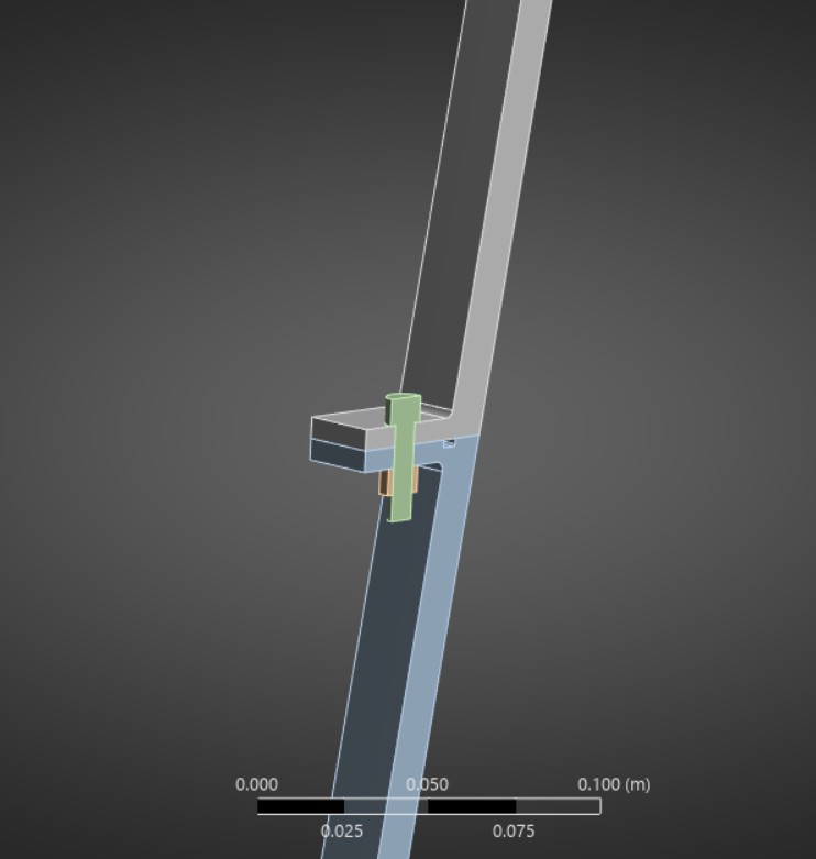
Middle section of rocket nozzle slice used for solving the model
3. Model & Mesh
After generating the auto-generated mesh by ANSYS, I added a few changes. The first change was adding a specific sizing to the nozzle and the bolt & nut, with the bolt & nut having a mesh with an element size that is roughly three times finer than the nozzle body. The other change that I made was to add a hex dominant method to the entire geometry, as a cleaner mesh is achieved in this case. The mesh had a total of 26134 nodes and 4255 elements. Additionally, a frictionless boundary condition was added where the mid and top parts of the nozzle meet near the bolt to conduct a more rigorous test of the model. The force from the regen channel was also included in the analysis.
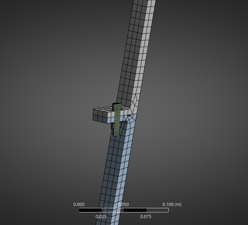
Middle section mesh of the rocket nozzle slice
4. Results
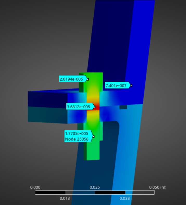
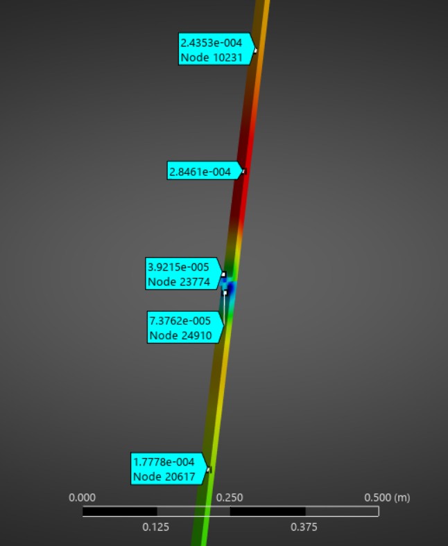
For the analysis, I split the loading stages of the nozzle into three steps. The first step is the initial condition (including bolt pretension), the second having the regen channels flow with fluid as well as the pressure increasing in the nozzle (82.9 kPa at the bottom of the nozzle and 329.02 kPa at the top), and the third step adding in the temperature increase of 350 degrees celsius. All values were determined by data from the engine’s actual use. The results of the deformation, gap at the regen channel, and von mises stress distribution are shown below.
The results revealed that after the third time step, there might come to be a gap that is too big near the regen channel, which may cause some problems, as fuel could leak or could mix with oxidizer. However, that result is likely because of the frictionless boundary condition, and in a further analysis that would need to be refined, because, after all, the F-1 engine did see flight and successfully sent astronauts to the moon.
Total Deformation at t=1
Total Deformation at t=2
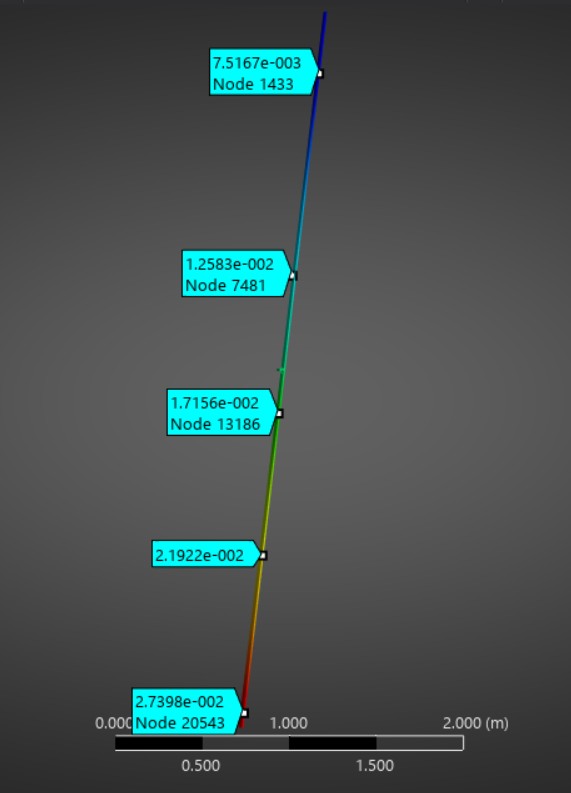
Total Deformation at t=3
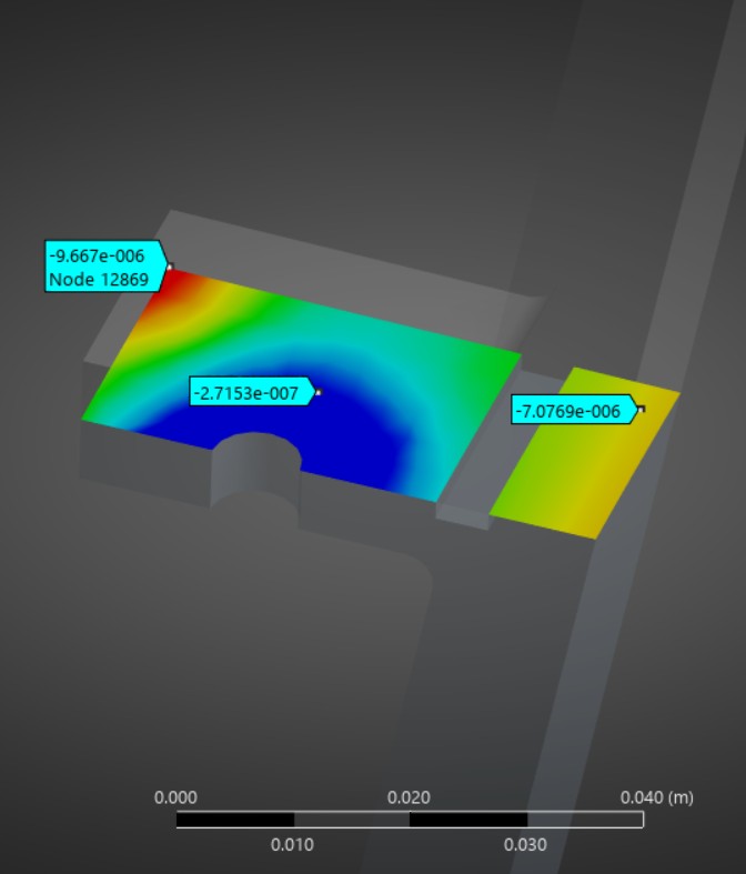
Gap at t=1
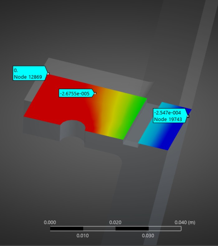
Gap at t=2
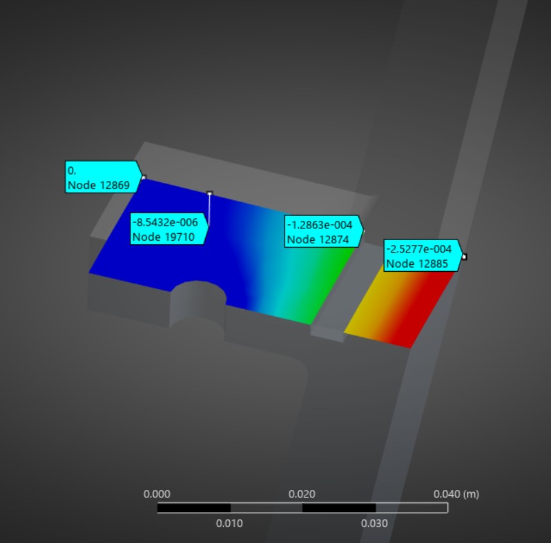
Gap at t=3
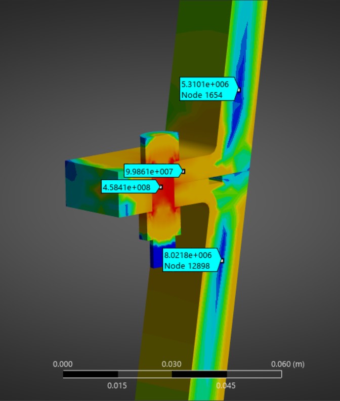
Von Mises stress distribution
Technologies Used: ANSYS Workbench, ANSYS Mechanical (Static Structural), Spaceclaim