Wind Turbine FEA
1. Engineering Data
Materials: A custom named material (named homogenous orthotropic; custom inputted youngs modulus and shear modulus) that represents the real material for a wind turbine blade.
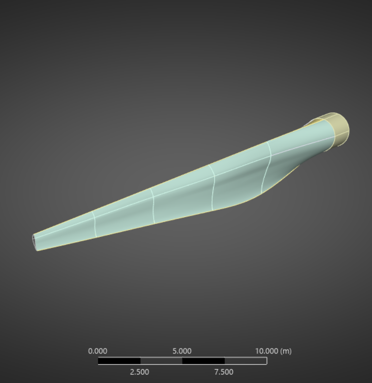
2. Geometry
The geometry is the wind turbine blade itself, and does not contain the fluid that surrounds the blade like the CFD analysis did.
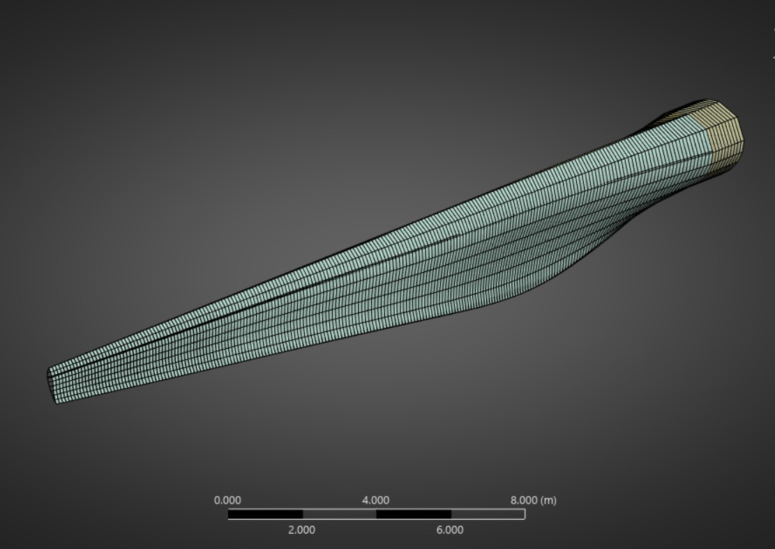
3. Model & Mesh
This mesh, due to the shape of the blade, was able to be made much more uniform with the majority of the elements conforming to a skewness of less than 10%. In order to obtain such a uniform mesh, a face meshing was utilized on the blade surface, as well as a custom mesh size of .2 m.
4. Results
I uses ANSYS to solve the mathematical model to find the deformation and stress in the wind turbine as a result of the pressures and forces as a result of the fluid the blade encounters. I found that the deformation was in the proper direction, so the FEA served as a confirmation that my CFD analysis was correct. Below, the results for the deformation and the Von-Mises Stress are shown. As illustrated, the maximum deformation occurs at the end of the blade (~.4 m) and the highest area of stress occurs at roughly 1/4 and 3/4 of the length of the blade.
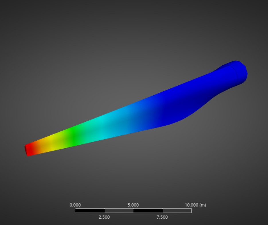
Deformation
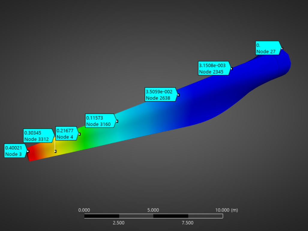
Deformation with probed values
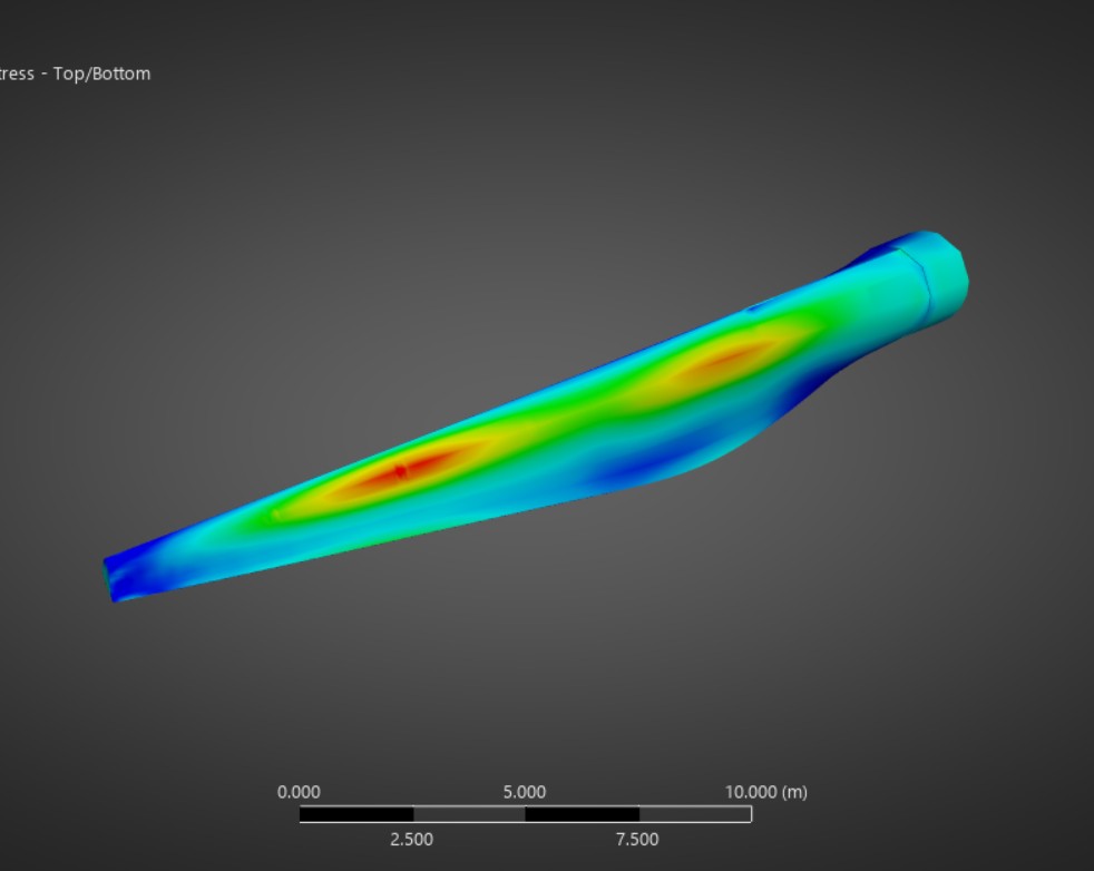
Von-Mises stress
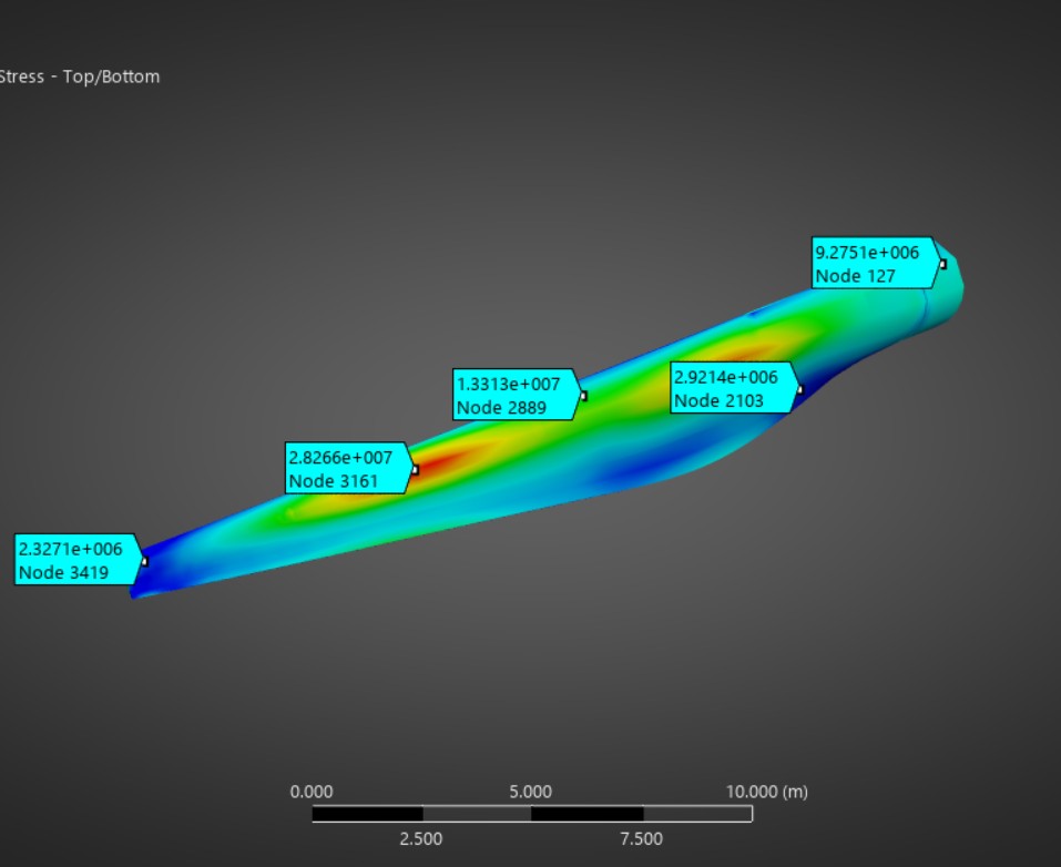
Von-Mises Stress with probed values
Technologies Used: ANSYS Mechanical