MAE 3270 Final Homework Part 2
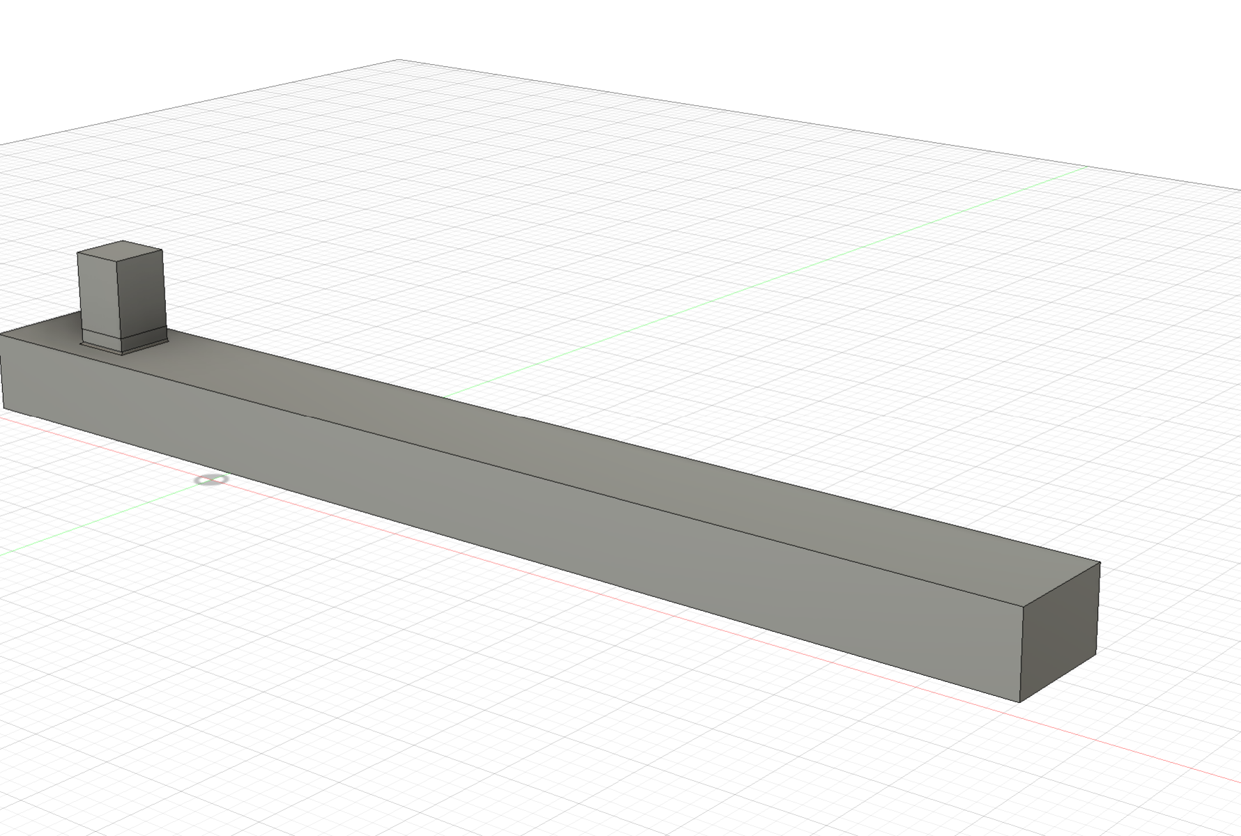
Image(s) of CAD model. Must show all key dimensions.

Total handle length (L): 16 in Width (h): 0.75 in Thickness (b): 0.50 in Gauge offset (c): 1.00 in Clamp region length: 0.40 in Gauge pad length: 0.60 in Gauge pad height: 0.50 in Fillet radius: 0.15 in Extra handle beyond load point: 3.00 in
Describe material used and its relevant mechanical properties.
Material: 7075-T6 Aluminum Elastic modulus (E): 10.4×10^6 psi Poisson’s ratio (ν): 0.33 Ultimate strength (reference): ~73 ksi Fracture toughness (reference): ~25 ksi·√in Fatigue strength at 1e6 cycles (reference): ~23 ksi Reason for choice: Lower E increases strain (and therefore mV/V) at the same stress and geometry, while maintaining required safety factors.
Diagram communicating how loads and boundary conditions were applied to your FEM model.

Normal strain contours (in the strain gauge direction) from FEM
Field shape: Tension on one side of the handle and equal-magnitude compression on the other; smooth through the prismatic span with mild perturbations near the clamp/fillet. Pad-average strains (improved design, 7075-T6):
- Gauge_Left: +1230 microstrain (µε)
- Gauge_Right: −1230 microstrain (µε) Half-bridge sensitivity (GF ≈ 2): 1.230 mV/V at 600 in·lbf (computed as 1000 × (GF/2) × strain = 1000 × 1 × 0.001230).
Contour plot of maximum principal stress from FEM
Peak location: Fillet/transition near the clamped region. Peak value: 13.6 ksi (≈ 93.8 MPa). In the gauge region, bending stress closely matches beam theory. The global peak is higher due to local concentration at the clamp/fillet.
Summarize results from FEM calculation showing maximum normal stress (anywhere), load point deflection, strains at the strain gauge locations
Max principal (normal) stress, anywhere: 13.6 ksi Gauge strains (pad averages): ±1230 µε Tip deflection at load point: 0.281 in (bending ≈ 0.2809 in; shear ≈ 0.0003 in) Half-bridge sensitivity (GF ≈ 2): 1.230 mV/V at 600 in·lbf
Torque wrench sensitivity in mV/V using strains from the FEM analysis
Gauge strains (avg): ±1230 µε Formula (half-bridge, GF ≈ 2): mV/V = 1000 × (GF/2) × ε Result at 600 in·lbf: 1.230 mV/V
Strain gauge selected (give type and dimensions). Note that design must physically have enough space to bond the gauges.
Type: Foil, 350 Ω, self-temperature-compensated for aluminum, polyimide backing Grid size: ~3 mm × 2 mm (≈0.12 in × 0.08 in) Placement: One gauge per side pad, aligned with beam axis, wired as a half-bridge (tension + compression arms) Pad/Surface: Flat pad ≥ 0.60 in × 0.50 in, surface finish ~32 µin Ra, flatness ~0.002 in
Technologies Used:
Back to Projects