Actuator Lever Arm
This project involved designing a two-dimensional lifting mechanism within a 150 cm by 50 cm workspace using a steel bar, three pin supports, and a linear actuator selected from an industrial catalog. The goal was to lift the maximum possible weight to the highest possible height, assuming all components were frictionless. By analyzing the geometry and static equilibrium of different bar and actuator configurations, the design optimized the actuator’s mechanical advantage to convert limited axial thrust into large lifting force. The project demonstrated how actuator placement and linkage geometry determine both lifting capacity and motion range, highlighting the trade-offs between force, stroke, and stability in mechanical design.
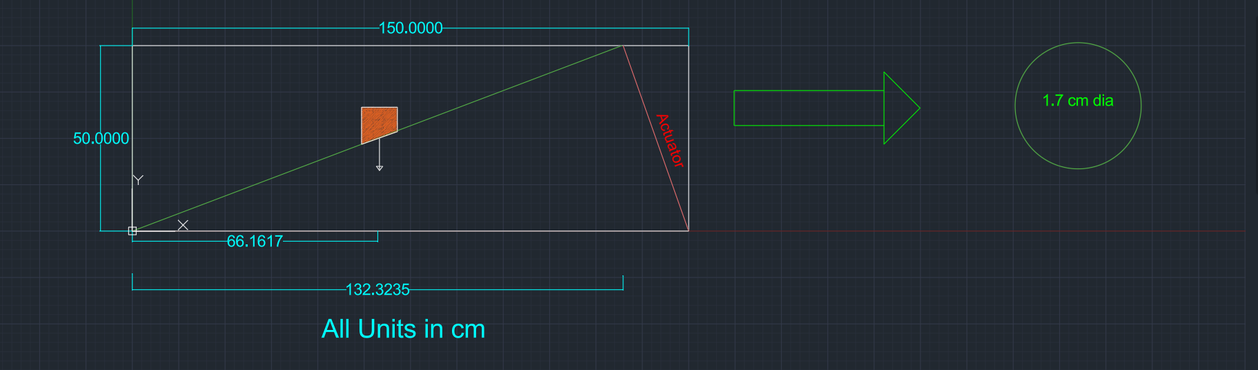
I started the project by designing my mechanish which pins the bar and actuator together while having the acutator and bar pinned on opposite sides of my design area. This allowed for a perpendicualr force from the actuator, providing the highest moment possible. I then decided to place the weight in the middle of the bar for the highest weight to get to the highest point. If the task needed to lift a larger weight it could be moved down the bar or up for a higher hieght and less weight.
I then did a force and moment balance to find the max weight my actuator could lift at the midpoint. The next part was designing what shape my bar should be based on the deflection needing to be less than or equal to 2% of its total length. Based on my design, I found my max deflection to be PL^3/48EI. I then solved for the moment of inertia and found the diameter of a thin walled cylinder to be 1.7 cm to fit all the criteria above.
Technologies Used: AutoCAD, Excel
Back to Projects