Summary
The goal of this project was to design a non-ratcheting torque wrench capable of meeting several design and performance specifications. I used a MATLAB script to perform analytical calculations and run through possible designs. I then created a CAD model in SOLIDWORKS and created a Finite Element Model (FEM) using Ansys Static Structural. I conducted analysis and then compared it to the results of the analytical calculations.
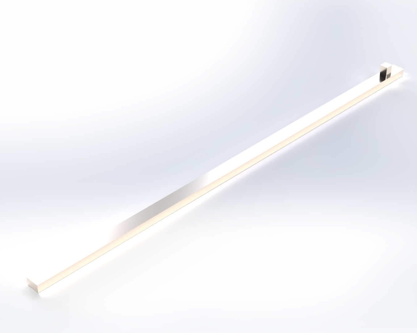
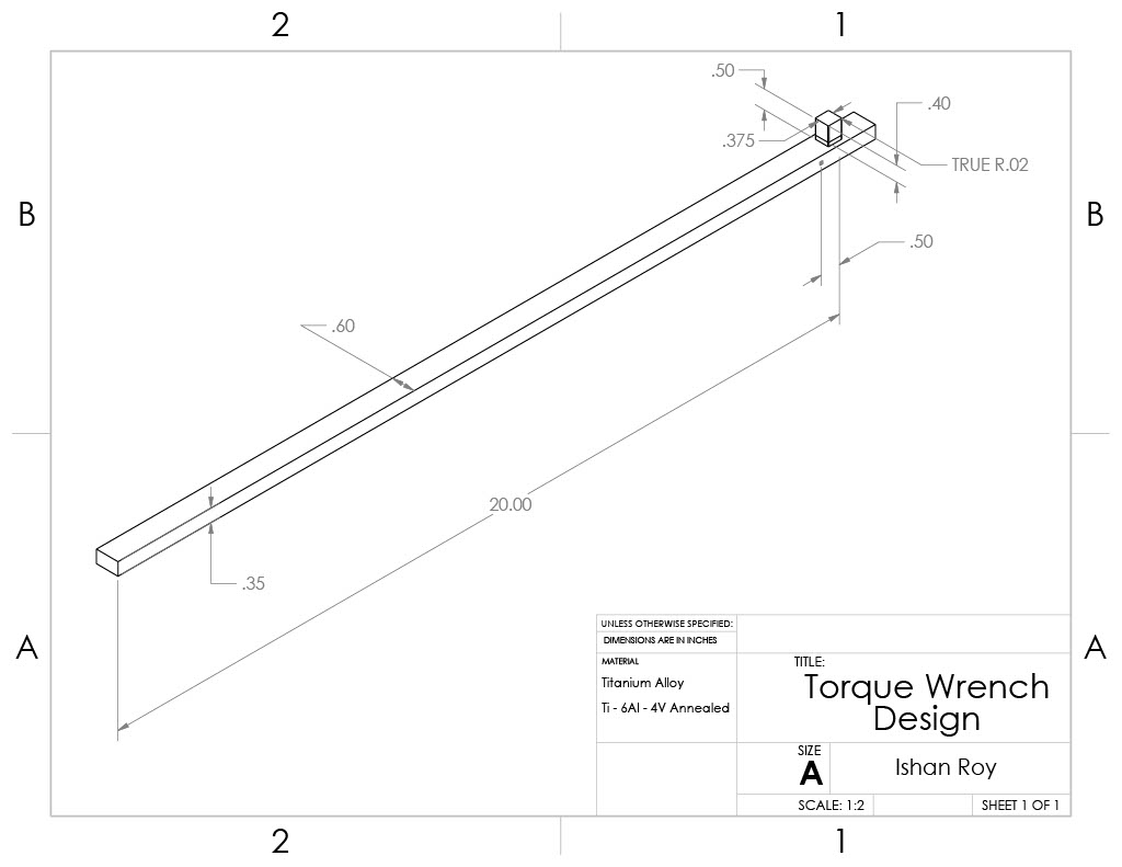
1) CAD Model
2) Material & Relevant Mechanical Properties
- Material: Ti-6Al-4V (Annealed)
- E = 119 GPa (= 17.3 Msi)
- ν = 0.31
- σᵧ = 910 MPa (= 132 ksi),
- Fracture toughness K₁C ≈ 107 MPa√m (= 97.3 ksi√in)
- Fatigue/Endurance limit ≈ 517 MPa (= 75 ksi)
- Source: Ansys Granta
Ti-6Al-4V (annealed) was selected for its high specific strength and corrosion resistance. With E = 119 GPa and ν = 0.31, it provides sufficient stiffness and produces measurable surface strain without approaching the allowable σy = 910 MPa under the applied loads. Some trade-offs, including the higher cost and lower modulus than steel, are acceptable given the goal of this project was to maximize the sensitivity of the design.
3) Finite Element Model Setup (Loads and Boundary Conditions)
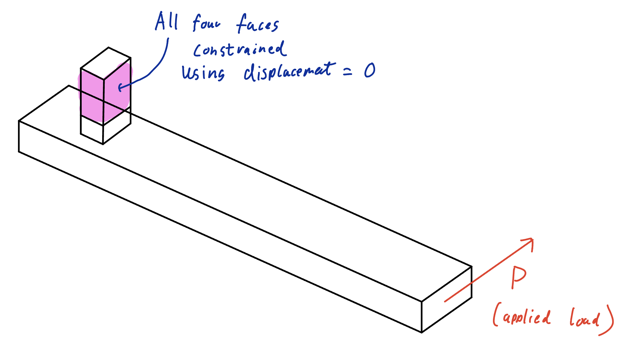
- Constraints: four faces of the block above the drive were constrained to have zero displacement
- Load: A load of 600 lbf * in was applied at the end of the wrench handle
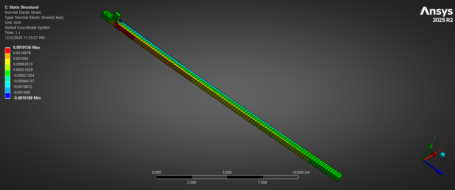
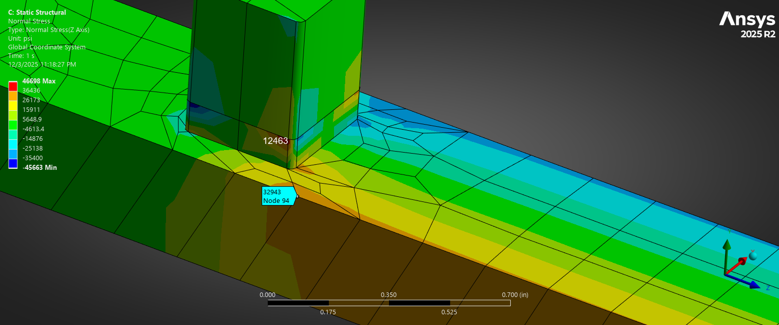
4) Normal Strain Contours
5) Maximum Principal Stress Contour
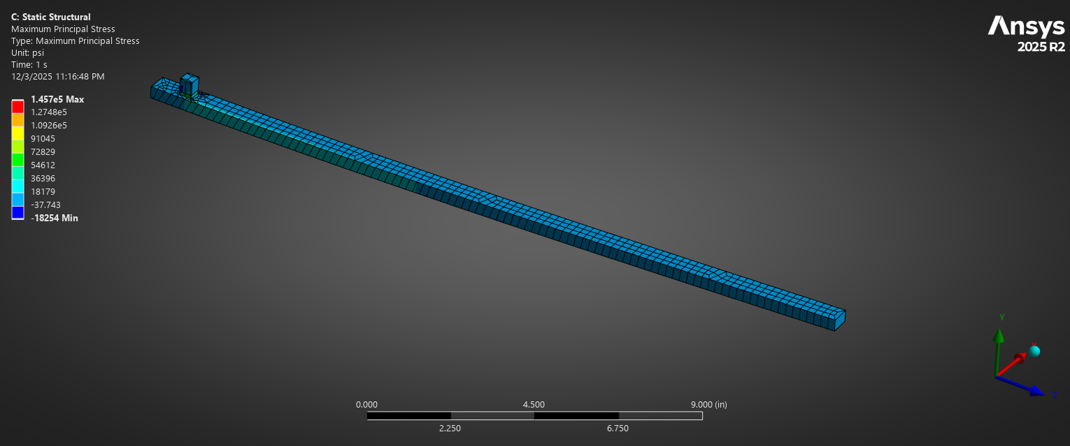
7) Max Normal Stress
- Value: 1.457 x 10^5 psi
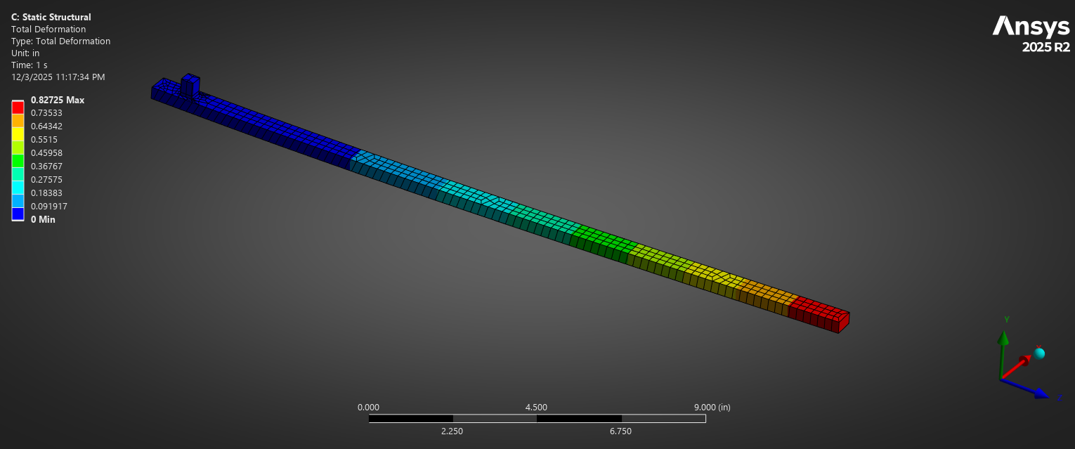
8) Deflection at Load Point
- Value: 0.8275 in
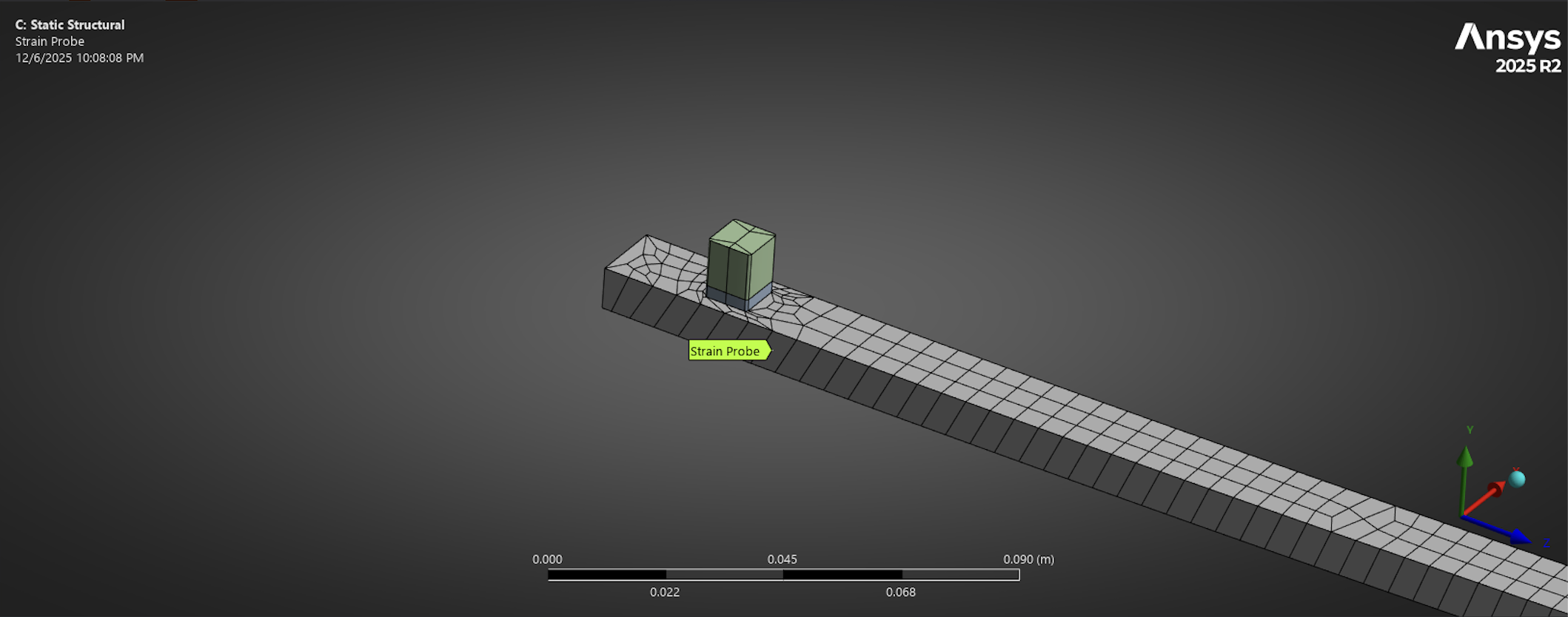
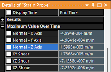
9) Strain at Gauge
- Value: 1599.3 µε at the set gauge location
10) Torque-Wrench Sensitivity
- Measured strain from the strain gauge in the model ε = 1599.3 µε
- Gauge factor: K = 2
- Bridge setup used: half
- Sensitivity: 1.5993 mV/V - meets the required criteria
11) Strain Gauge Selection
- Gauge Type: Bonded Foil Strain Gauge
- Dimensions: ~ 7mm x 4mm
- Bonding area on the part is larger than this, providing enough room