Massager Dissection
“Knead For Speed”
By Alexander Barry, Toby Huynh, Charles Valembrun, and Abha Bhole
Abstract:
We chose to analyze a massage gun for our system dynamics dissection. Specifically, we wanted to focus on the response of the vibrating tip and the voltage input.. The massage gun has six distinct modes that the user may select from, and we will be focusing on the lowest power setting of the massage gun for the analysis. The product consists of a DC motor, a linkage attached to an offset cam, a battery, and an electrical circuit board. The DC motor turns the offset cam which converts the rotary movement into linear pulsating vibrations. When testing the product, we noticed that applying a certain amount of force to the massage gun tip would cause the tip to vibrate with both a higher frequency and amplitude. We decided to further investigate this transition from the low to high frequency mode.
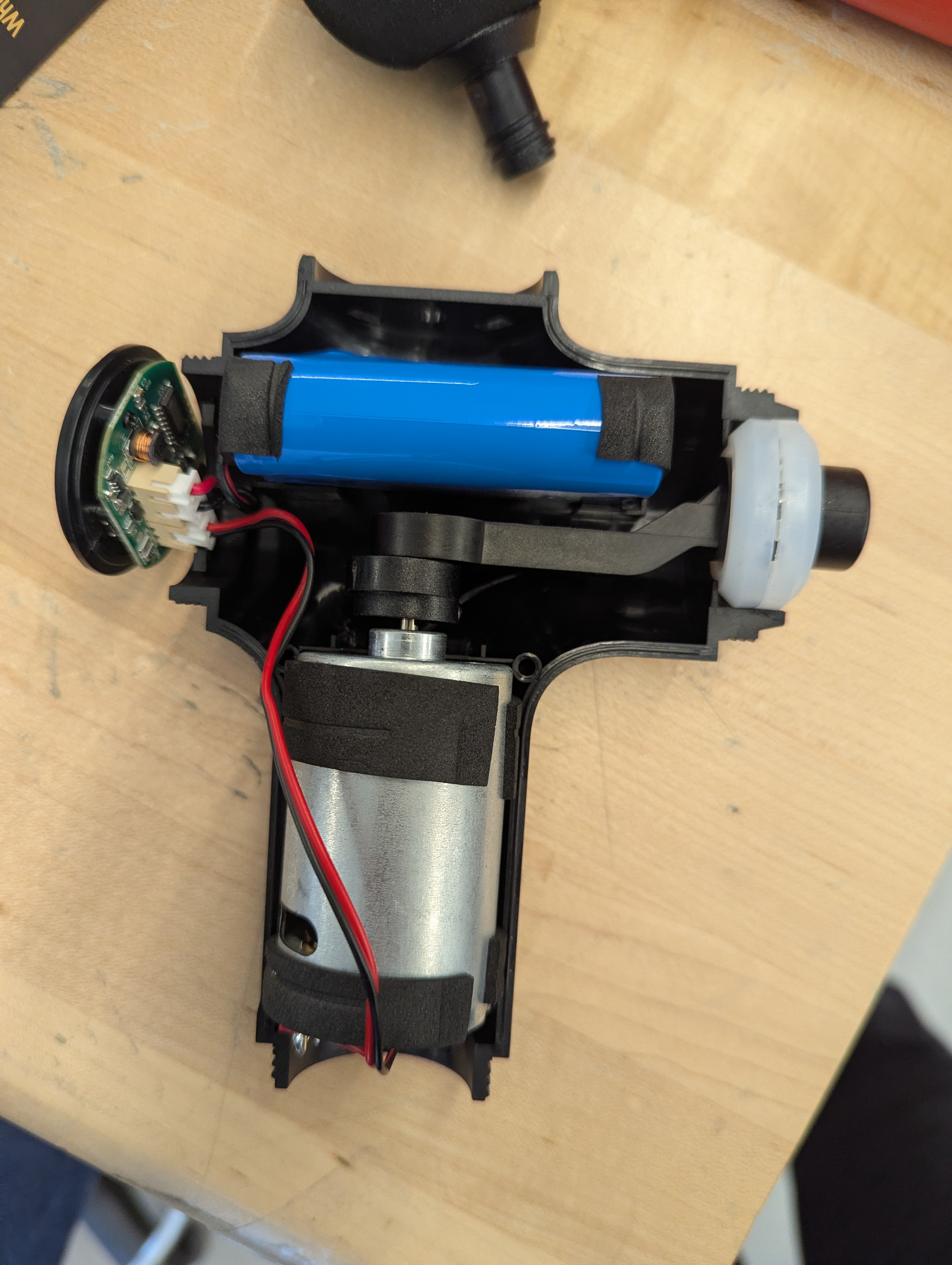
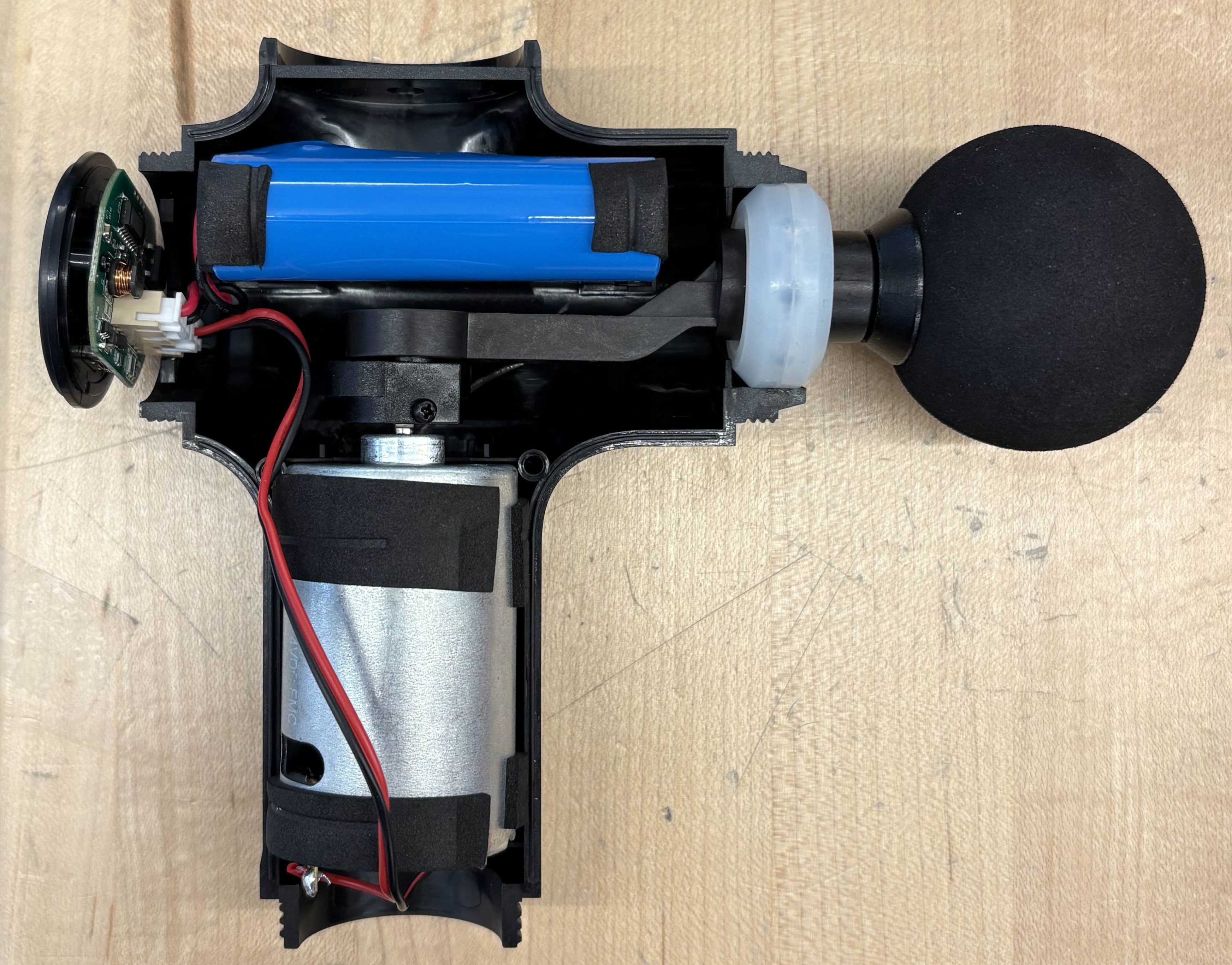
Figure 1: A cross-sectional view of the dissected massage gun.
Experimental Apparatus:
Our experimental apparatus consisted of two distinct systems that could both be analyzed using an oscilloscope. To visualize the vibrating tip of the massage gun, we taped an accelerometer to the massage gun attachment and recorded the trace of its acceleration as a function of time as seen in Figure 2. To visualize the voltage across the DC motor, we removed the bottom cover of the massage gun and connected two leads from the motor to the oscilloscope directly. We recorded the voltage across the motor as a function of time and specifically focused on the transition period from the “regular mode” to the “fast mode”.
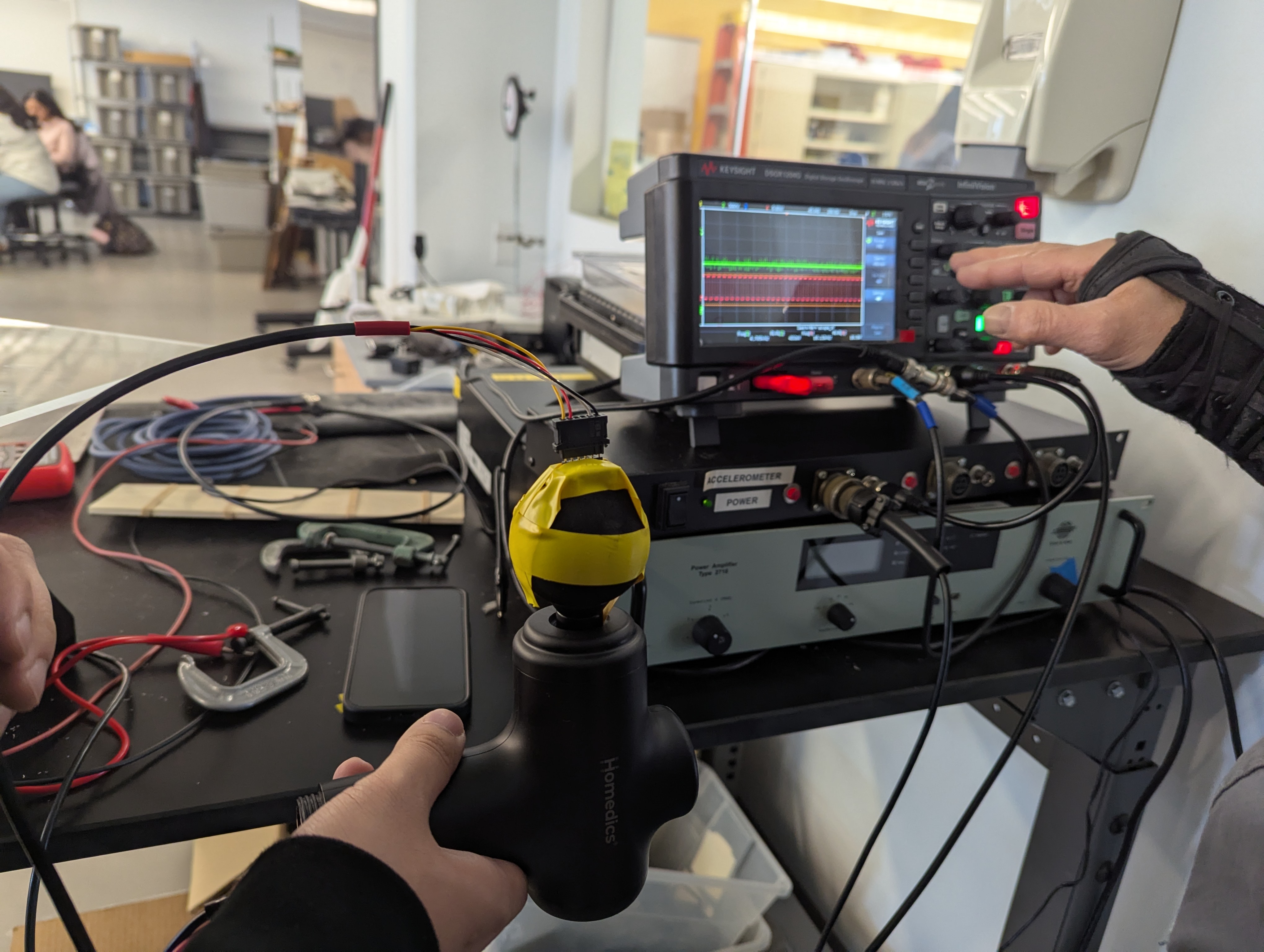
Figure 2: Our experimental setup
Figure 3 below clearly shows the responses for both the “regular mode” to “fast mode,” including the transition period. The frequencies are 21.6 1/s and 43.2 1/s for the “regular mode” and “fast mode,” respectively. However, the time scale of the transition between the modes is very small compared to the time scale of the oscillations measured by the accelerometer. The response appears to get to steady state within a single period, and we were unable to obtain a value for the time constant from this data.
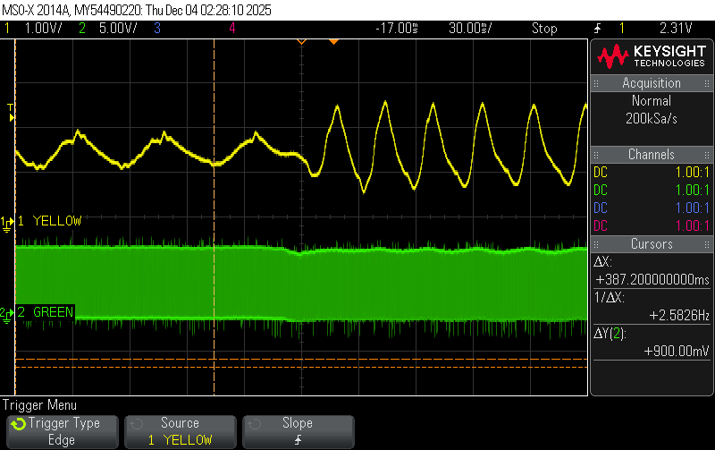
Figure 3: Change in response as measured by the accelerometer after applying a disturbance force to the head of the massage gun.
This led us to change our approach to instead focus on measuring how the applied voltage to the motor changed during that transition, instead of how the response of the motor changed. At this point we were able to notice that the input voltage signal was on a duty cycle, which changed how we went about analyzing the system.
Analysis of the DC motor duty cycle:
The speed of the motor is controlled by a duty cycle using pulse width modulation. This is a signal type that alternates between 0V and a set nonzero voltage, with the ratio of time the signal is ‘active’ to the total period being defined as the duty cycle value, as shown in Figure 4 below. Pulse width modulation is a way to modify the average voltage being sent to the motor, with longer pulses (corresponding to higher duty cycles) resulting in higher average voltage. For a DC motor such as the one in the massage gun, voltage controls speed and current controls torque. That explains why the higher average voltage causes a higher speed output from the motor, which is how the motor can run at different speeds with the same value of DC voltage signal.
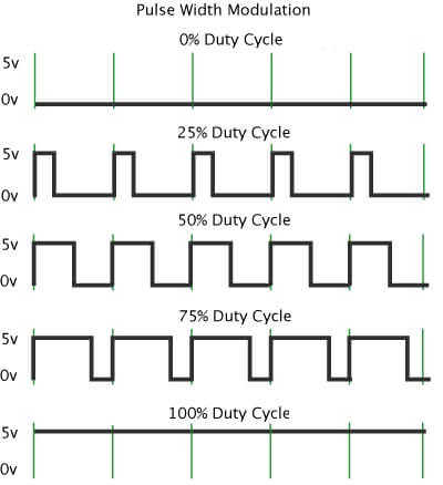
Figure 4: Diagram depicting the pulse width of signals for different values of duty cycles.
(https://circuitcrush.com/pwm-tutorial/)
To most accurately determine when and how the switch from the low frequency mode occurs, we needed to determine when the duty cycle of the DC motor began to increase and how long the duty cycle took to stabilize. However, the resolution of the exported CSV file corresponding to Figure 3 was insufficient due to the high frequency rate of the motor voltage output compared to the time scale set on the oscilloscope. From the oscilloscope, we knew that the duty cycle transitions from 44% to 84%, but the time scale over which this happens was too small and the frequency of the square wave voltage output was too high. To fix this, we collected more data, this time with a smaller time scale on the oscilloscope so we could better characterize how the duty cycle changes during the quick transition. We focused only on the transition period and recorded the time when the duty cycle reached specified values, which we chose to be 2% increments starting from 44% duty cycle to 84% duty cycle. A graph of the % duty cycle vs time data plotted is shown below in Figure 5.
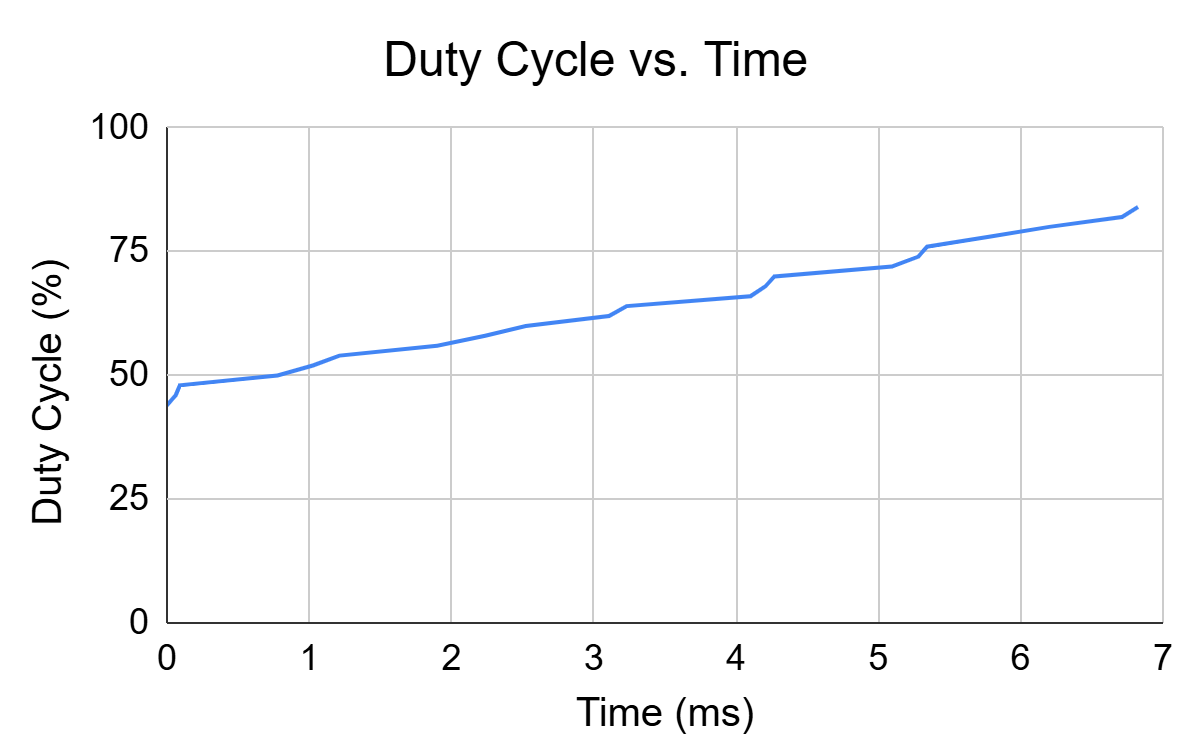
Figure 5: Duty cycle vs time during the transition between “regular mode” and “fast mode.”
We were surprised by the correlation the plot showed, wich looked more linear when we expected a relationship that looked more exponential.
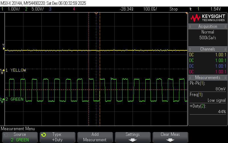
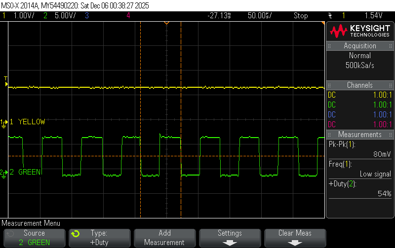
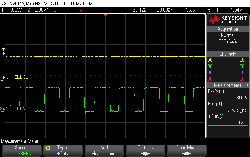
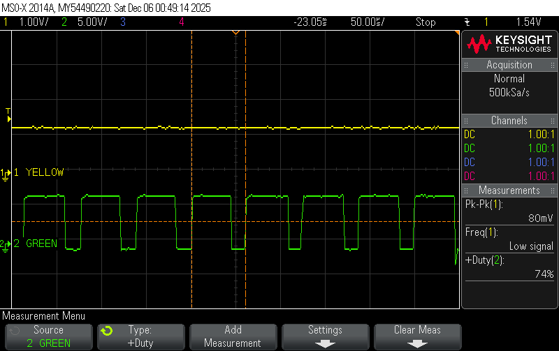

Figure 6: Oscilloscope snapshots every 10% increase in duty cycle during the transition period (From 44% to 84% Duty Cycle)
Analysis of the Massage Gun Vibration:
Slow mode
Period of oscillation in the slow mode: T1 = 0.0465 seconds (average period over 4 cycles)
Frequency of the slow mode: f1= 1/0.0465 = 21.505 Hz
Amplitude of the slow mode: A1= 0.3705 V
Fast Mode
Period of oscillation in the fast mode: T2 = 0.0235 seconds (average period over 4 cycles)
Frequency of the fast mode: f2= 1/0.0235=42.553 Hz
Amplitude of the fast mode: A2= 1.024 V
The fast mode operates at approximately 3 times the frequency of the slow mode. The amplitude gain of 176% demonstrates that the system gain is dependent on the frequency and possibly suggests consistency with a second order mass spring damper system approaching resonance. On the other hand, there may be disturbance rejection being utilized in the controller which is causing the motor to generate a higher force in the fast mode to compensate for the increased damping caused by the force on the massage gun tip from the increase in oscillation speed. When the massage gun is in slow mode, it is oscillating in air without much resistance. In contrast, the fast mode activates when the massage gun tip is in contact with a surface, in which the surface applies a disturbance force on the tip. The disturbance load changes the dynamics of the system where a larger force is required to maintain oscillation. From a functional standpoint, it makes sense that the massage gun exhibits two distinct operating regimes since the user would want a deeper massage (higher amplitude and frequency) the moment they press the massage gun into their desired point of contact.
Block Diagram
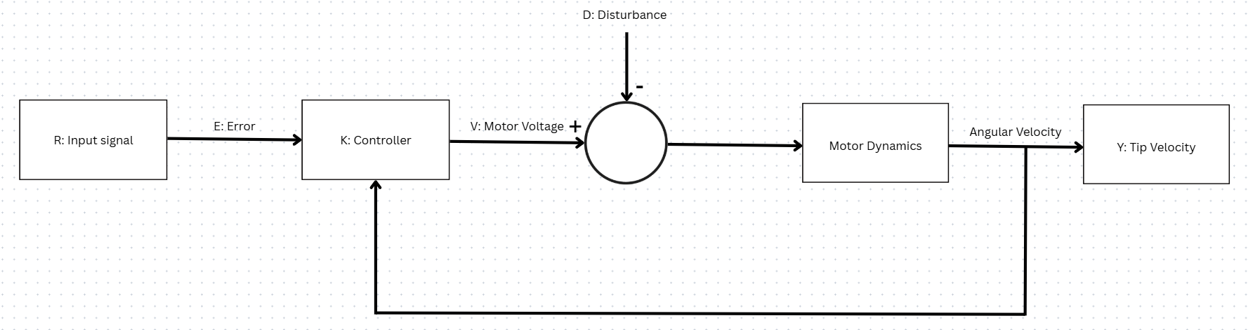
Figure 7: Proposed block diagram for our massage gun system.
Essentially, when the massage gun tip is pressed against a surface, the applied force acts as a mechanical disturbance to the system. This disturbance is detected by changes in motor behavior, and in response, the controller increases the duty cycle of the PWM voltage supplied to the DC motor, which increases average motor voltage and resulting angular velocity. This leads to a rapid increase in oscillation frequency and amplitude at the massage gun tip. We did not examine the electronics involved in detail, but this behavior indicates the presence of a closed-loop control system that responds to increased mechanical load. Adding a disturbance therefore functions as an ‘on’ switch which triggers the required massage frequency.
We can simplify the model of the mechanical system to a mass-spring-damper system for the linear motion of the linkage that connects to the massage gun tip, described by the equation mẍ+bẋ+kx = Fdrive(t)+Fdis(t). The transfer function of this would be Gmech(s)=X(s)F(s)=1ms2+bs+k. There would be a resonant frequency for this system around =km. This resonant frequency can be used in the design to amplify the amplitude of oscillations. The fast mode may have been located near, but not directly at a resonant frequency to achieve higher amplitude of oscillations when in contact with a surface. Neither of the modes would be directly located at a resonant frequency because of structural issues that may arise at this frequency. Driving the system at resonant frequency would cause stability issues with the amplification of the oscillation amplitude, as well as wear and tear of the material. A more complex control law for the motor is most likely used alongside this to create a safe and consistently performing design for the massage gun.
References:
Brian (2018). PWM Pulse Width Modulation Tutorial | Circuit Crush. [online] Circuit Crush. Available at: https://circuitcrush.com/pwm-tutorial/ [Accessed 8 Dec. 2025].
Technologies Used: System Dynamics, Controls, Experimentation
Back to Projects