Wrench Redesign
As a final project for MAE 3270, Mechanics of Materials, I was tasked with analyzing a design for a torque wrench and designing an improved version. I used both hand calculations and ANSYS FEM simulations to perform the analysis.
I wrote a MatLab script that iteratively determines the ideal geometries for the design to meet safety factor requirements as closely as possible and avoid unnecessary over-engineering. I developed the new design for the wrench in CAD, and imported it into ANSYS to perform FEM on it.
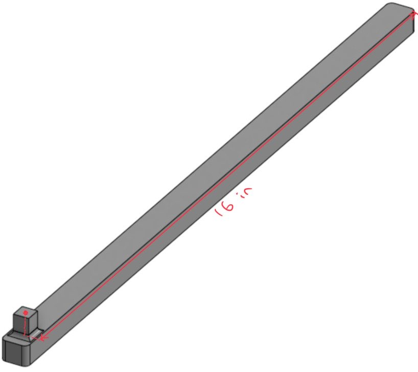
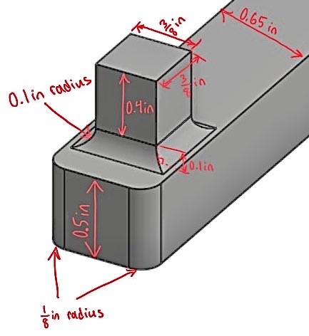
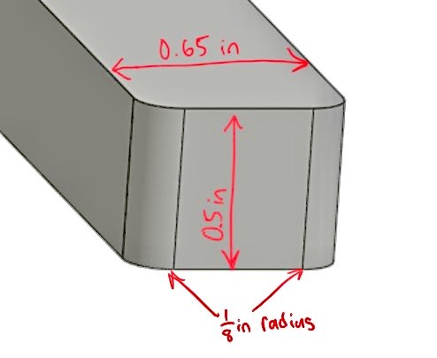
1) CAD Model
Below are the CAD model images showing all relevant geometry and dimensions:
2) Material and Mechanical Properties
The redesigned wrench uses M42 Steel, with the following mechanical properties:
- Young’s Modulus: 32×10⁶ psi
- Poisson’s Ratio: 0.29
- Ultimate Tensile Strength: 370×10³ psi
- Fracture Toughness: 15×10³ psi√in
- Fatigue Strength (10⁶ cycles): 115×10³ psi
- Fatigue exponent b: –0.138
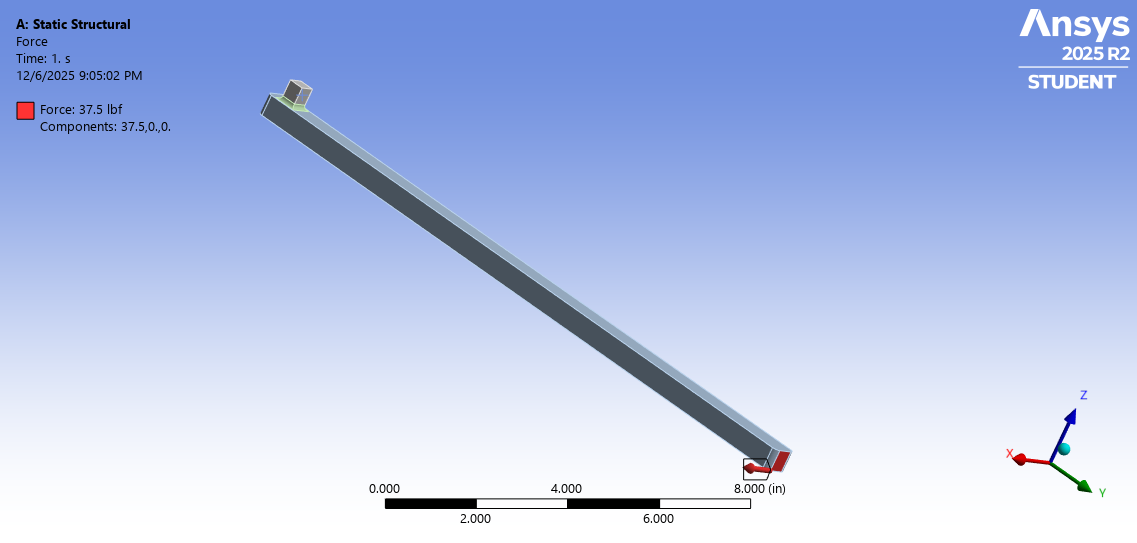
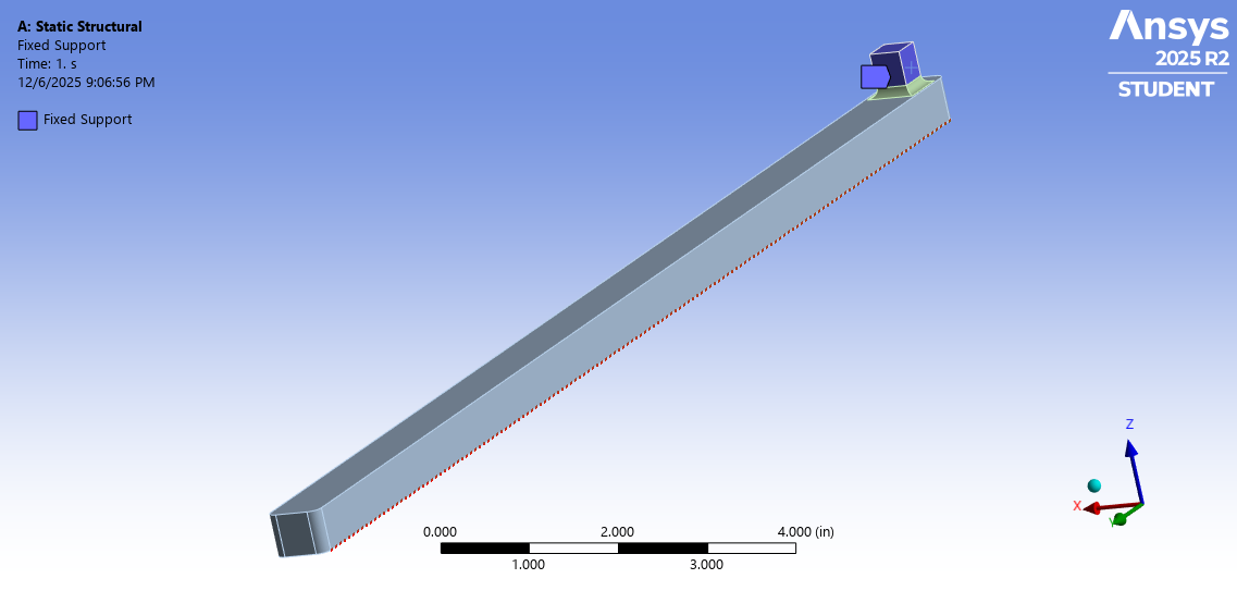
3) FEM Load & Boundary Conditions
A load of 37.5 lbf in the +x direction was applied at the handle tip.
The socket was set as a fixed support for the boundary condition.
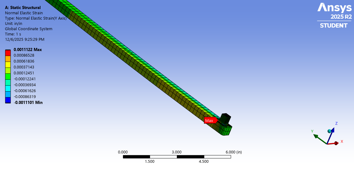
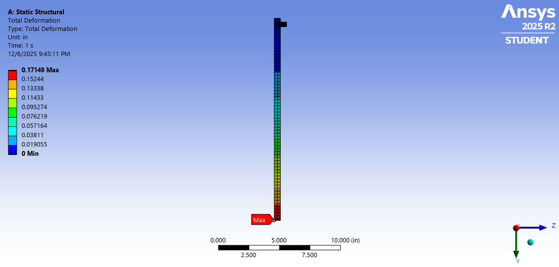
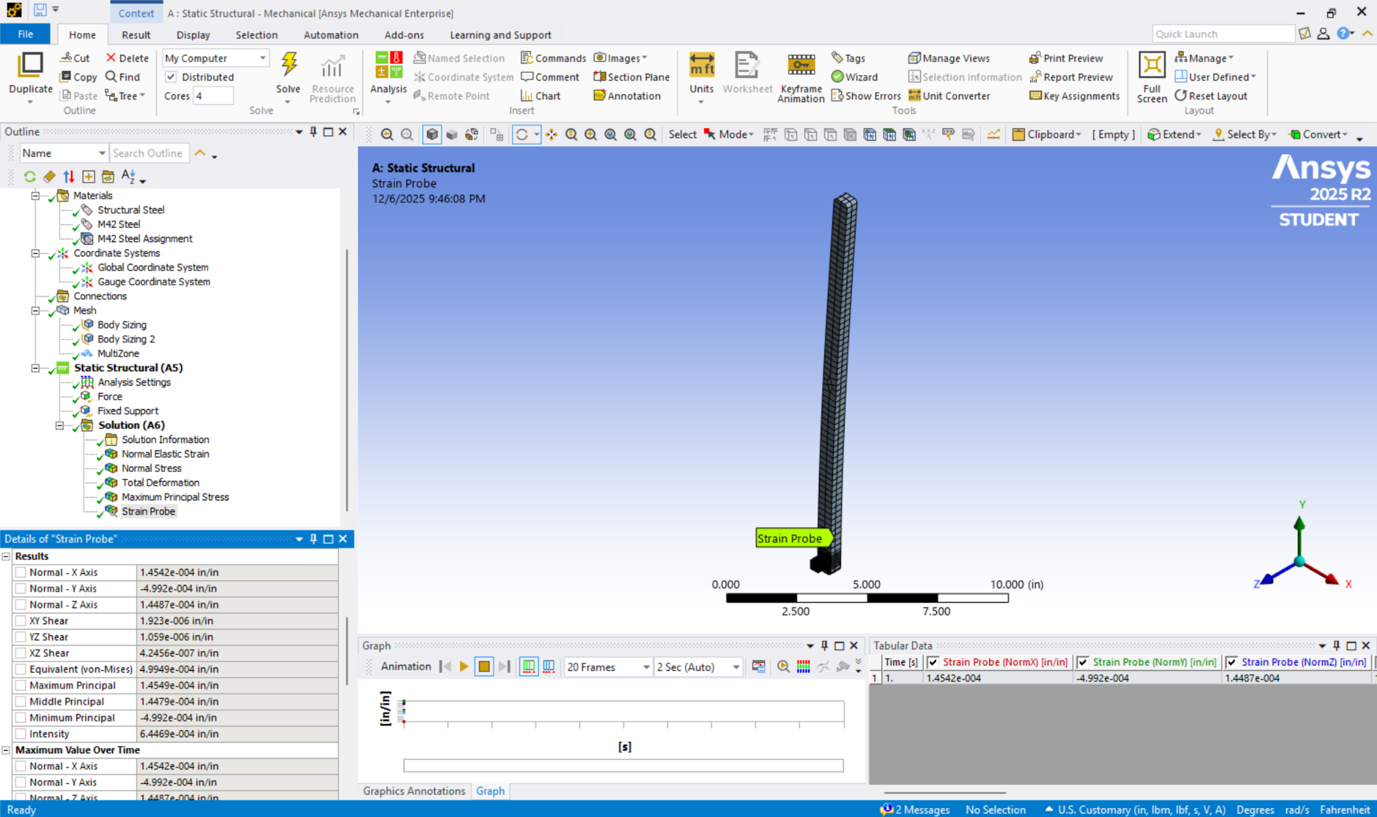
4) Normal Strain Contours
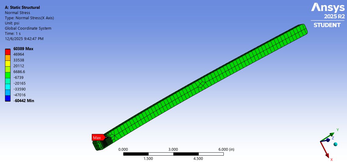
5) Maximum Principal Stress Contour
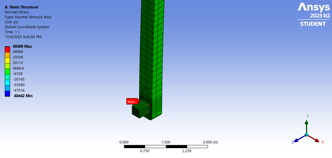
6) Summary of FEM Results
- Maximum normal stress: 60.4 ksi
- Concentrated primarily at the socket-to-body interface due to boundary conditions
- Outside this region, stresses remained below 7 ksi
- Load point deflection: 0.171 in
- Strain at gauge location: –499 µε
7) Strain Gauge Sensitivity (mV/V)
Using the FEM-obtained strain and aligned strain-gauge orientation:
The strain gauge is predicted to read a value of 0.499 mV/V under the defined loading.
8) Strain Gauge Selection
The chosen gauge is the Precision Strain Gauge by Omega with a size of 4.7 mm (SGD-1.5/120-LY41). Our redesigned wrench geometry has enough area to bond this strain gauge in the desired area.
Technologies Used: CAD, ANSYS FEM
Back to Projects