Torque Wrench Design
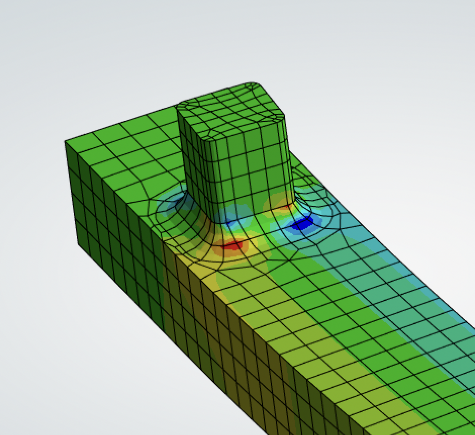
For our MAE 3270 final design project, we were tasked with creating a 3/8-inch drive torque wrench capable of sustaining ±600 in-lbf while producing a measurable strain-gauge output of at least 1.0 mV/V. The project combined analytical design, fatigue & fracture analysis, materials selection, CAD modeling, and FEM verification.
To begin, I performed full hand calculations based on beam theory to estimate bending stresses, strains at the gauge locations, fatigue safety factors, and crack-growth resistance. These calculations guided selection of the wrench geometry and helped refine parameters such as handle thickness b, width h, and the strain-gauge distance c. I automated this process using a MATLAB script to iterate dimensions and compare materials including steels, aluminums, and titanium alloys.
CAD Model and Key Dimensions
Using Autodesk Fusion 360, I developed a complete CAD model of the wrench. The model includes all major design features such as the rectangular handle, strain-gauge flats, and the 3/8-inch square drive.
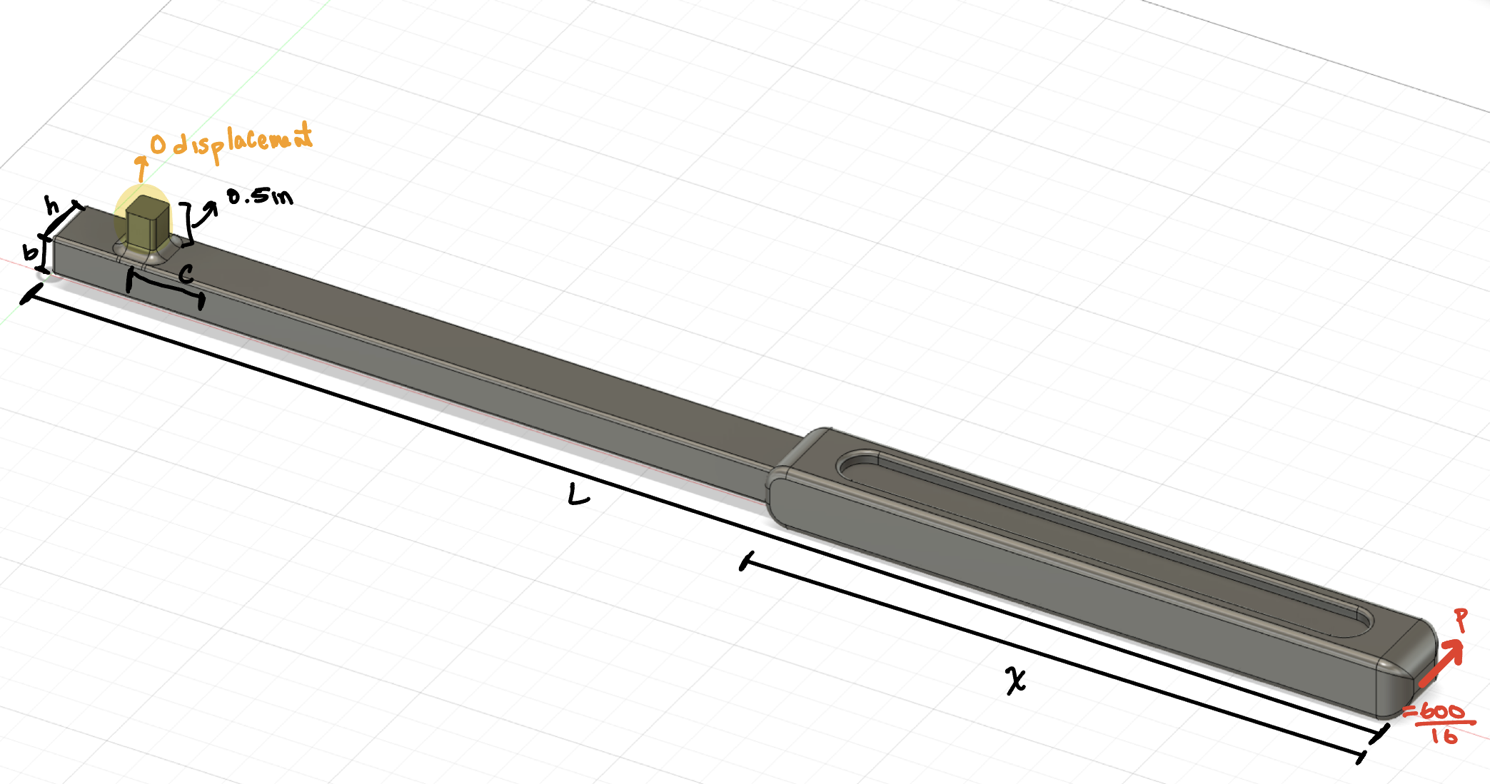
Key dimensions shown in the CAD drawing include:
- Length from drive center to load point, L = 16 in
- Handle width h = 1 in
- Handle thickness b = 0.5 in
- Strain-gauge distance c = 1 in
- Handle Length W = 8 in
- Equivalent Force P = M/L =37.5lbf (red)
- Yellow = Boundary condition of zero displacement
These dimensions were driven directly by my analytical design script to balance stress constraints and sensitivity requirements.
Material Selection & Relevant Properties
I selected Aluminum 7075, based on its strength, fatigue resistance, and fracture toughness, ensuring all three safety factors were met:
Values Found from Granta:
- Young’s Modulus (E): 10.5E6 psi
- Fatigue Strength (10⁶ cycles): 28E3 psi
- Fracture Toughness (K_IC): 24.3E3 psi√in
- Poisson’s Ratio: 0.33
These hand calculations proved this material allowed the wrench to survive fully reversed ±600 in-lbf loading with:
- Yield/brittle failure safety factor ≥ 4
- Crack-growth safety factor ≥ 2
-
Fatigue safety factor ≥ 1.5
- FEM analyses would prove later that these values vary in reality and further iteration of the part is neccesary.
FEM Boundary Conditions and Applied Load
The CAD model was imported into ANSYS Discovery for finite element analysis.
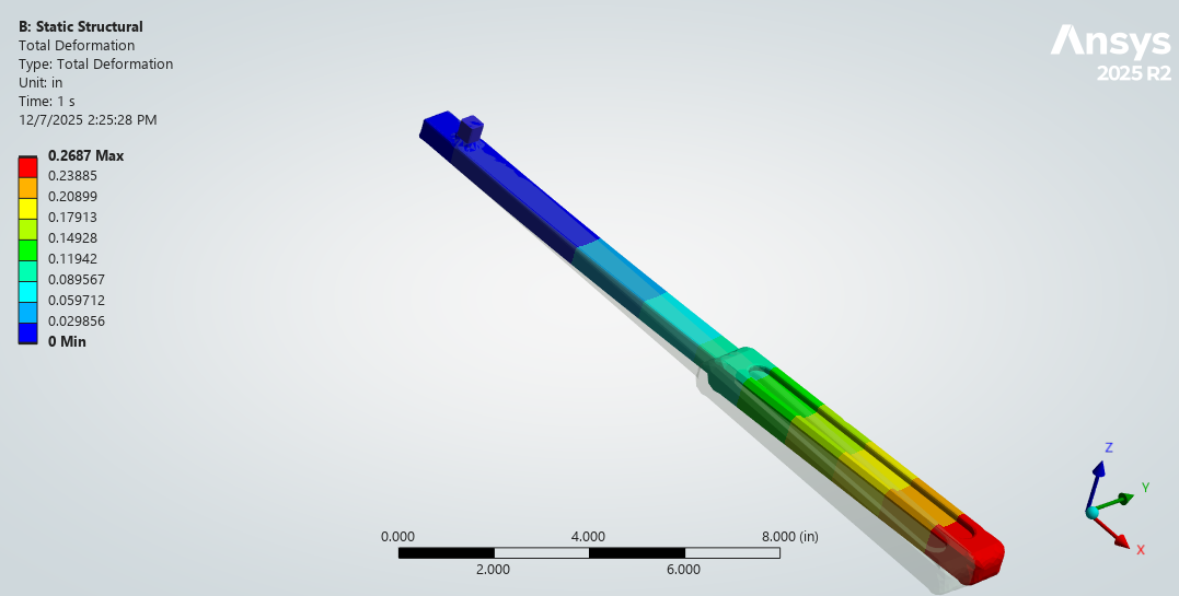
The FEM model used:
- Clamped boundary condition at the upper 0.4 inches of the drive head (per assignment spec)
- Applied force equivalent to 600 in-lbf torque which meant F = T/L
Normal Strain Contours at Gauge Locations
To compute the output voltage, I extracted normal strain in the longitudinal direction at the gauge mounting surfaces.
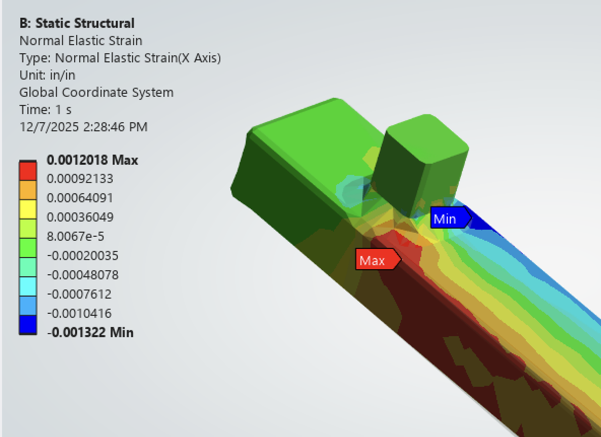
The FEM results revealed the precise strain distribution around the narrowed gauge region and allowed an accurate calculation of mV/V sensitivity.
Maximum Principal Stress Contour
A principal stress contour plot was generated to verify the wrench remained within strength limits.
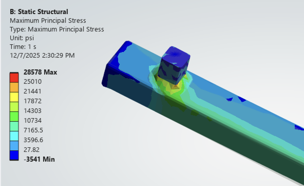
Peak stresses occurred near the transition between the drive head and handle. These stresses were compared directly with hand-calculation values to evaluate beam-theory accuracy.
Summary of FEM Results
From the final refined mesh, ANSYS produced:
- Maximum principal stress: 28.5 ksi
- Load-point deflection: 0.2687 in
- Strain at gauge location: 893.8 microstrain
- Comparison to hand calculations:
- Stress values differed by 25.7% from Beam Theory vs. FEM
- Deflection differed by 3.0%
FEM giving lower stress than beam theory due to 3D load distribution and filleted geometry reducing the peak surface stress.
Torque Wrench Sensitivity (mV/V)
Using the FEM strain results and assuming a half-bridge configuration:
Output(in mv/V) = GF * ε * 1000 * 2.1
Where:
- GF is the gauge factor of the selected strain gauges
- ε is FEM strain at gauge surface
- 2.1 is the assumed Bridge Factor
Final sensitivity:
0.93 mV/V at 600 in-lbf
This value is less than the required 1.0 mV/V from the project details which will require further iteration in the future.
Strain Gauge Selected
I selected the SGD-1.5/120-LY13, with:
- Gauge factor: 2.1
- Grid length: 1.5 mm
- Resistance: 120 Ω
- The main reasoning for the choice of strain gauge in this project was the size constraint
The design ensured there was sufficient flat surface for gauge bonding and appropriate strain levels for reliable measurement.
Actual Gauge Link: Click here
This project demonstrated full integration of materials engineering, classical mechanics, CAD design, strain-gauge instrumentation, and finite-element analysis—while requiring careful iteration to balance sensitivity with structural reliability.
Open full Report: MAE-3270-Wrench-Analysis
Technologies Used: Autodesk Fusion, ANSYS, MATLAB
Back to Projects