RC Car System Modeling
ODEs, State-Space, and TFs
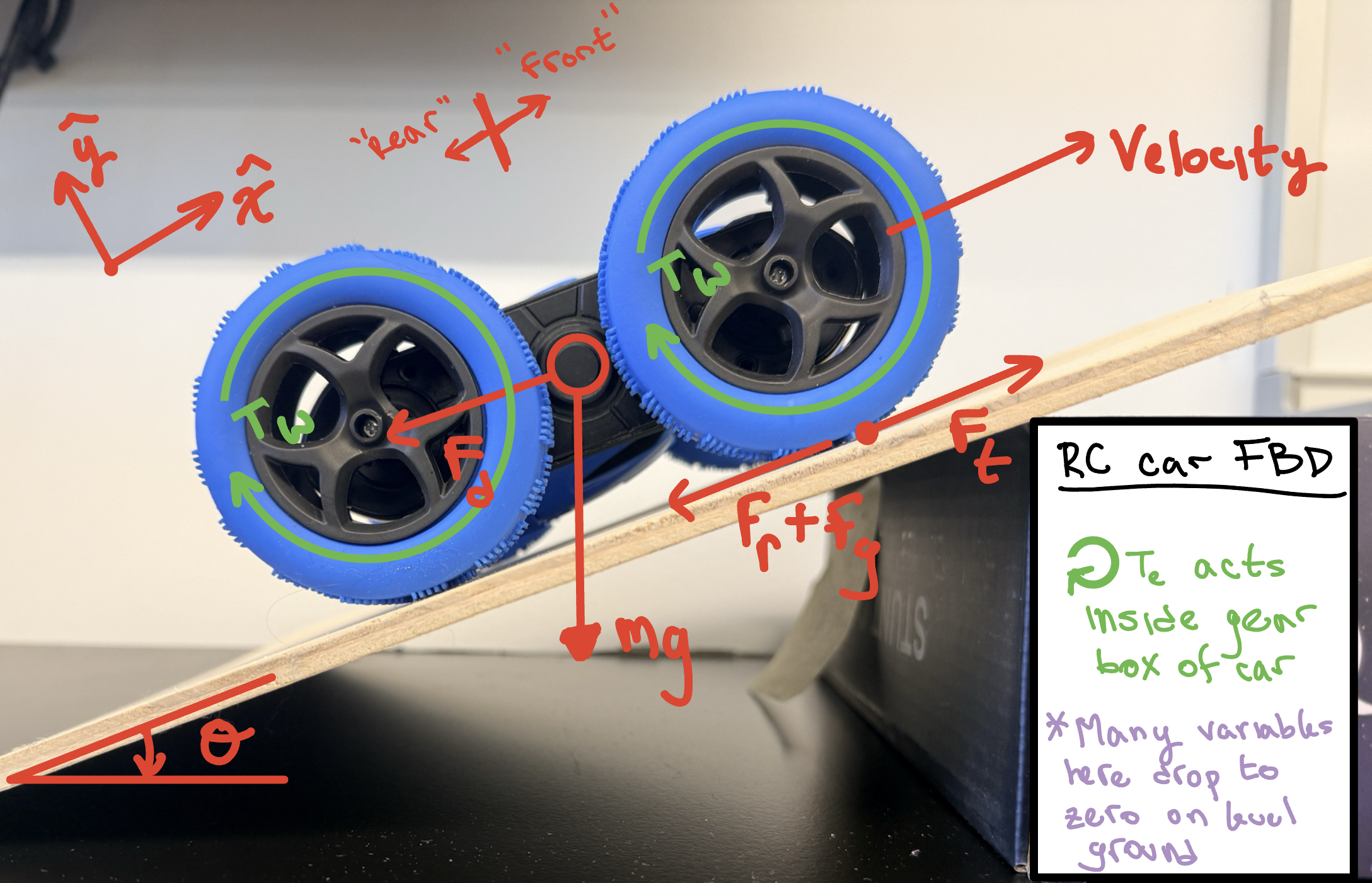
This project develops a simplified dynamic model of a small RC car by combining two main components: the vehicle’s longitudinal motion and the internal electrical behavior of the DC motor. The modeling begins by describing how the car accelerates based on the balance between the traction force produced at the wheels and any resisting forces. For a lightweight RC car operating on flat ground, most resisting forces such as drag, rolling resistance, and slope effects are negligible, allowing the model to focus primarily on traction.
Rotational dynamics are then added through the wheels and motor shaft. The wheel speed is tied directly to vehicle speed under the assumption of no slipping. The motor contributes torque through its gear ratio, and both wheel inertia and motor inertia contribute to the car’s effective resistance to acceleration.
The DC motor itself is modeled using standard electrical and mechanical relationships, including how current responds to applied voltage and how that current produces torque. These relationships are combined so that the motor’s electrical behavior directly affects vehicle acceleration.
Finally, the system is written in state-space form using two states: motor current and vehicle speed. This allows the entire RC car system to be represented as a compact set of first-order equations suitable for simulation and control analysis. A transfer function relating input voltage to vehicle speed can also be derived from this formulation.
Open full PDF: RC Car ODE and State-space Analysis
Technologies Used: Control Systems Modeling
Back to Projects